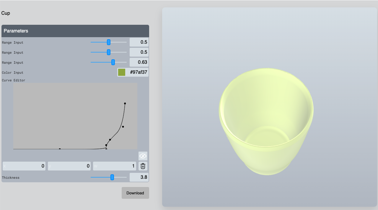
Let’s create a parametric cup model on BeeGraphy parametric node-editor software
- 3D modelingExperience
- May 22, 2022
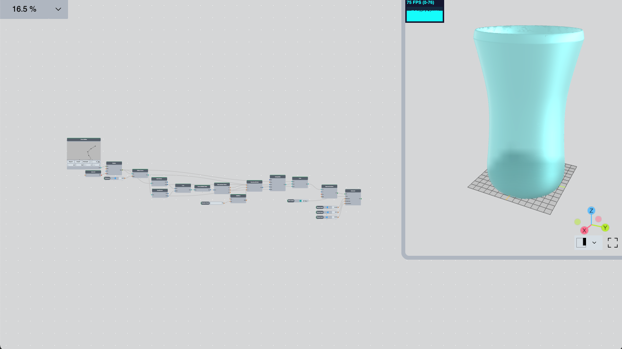
To create a parametric model of the coffee/teacup, you need to use the following nodes and connections in the BeeGraphy parametric modeling online software.
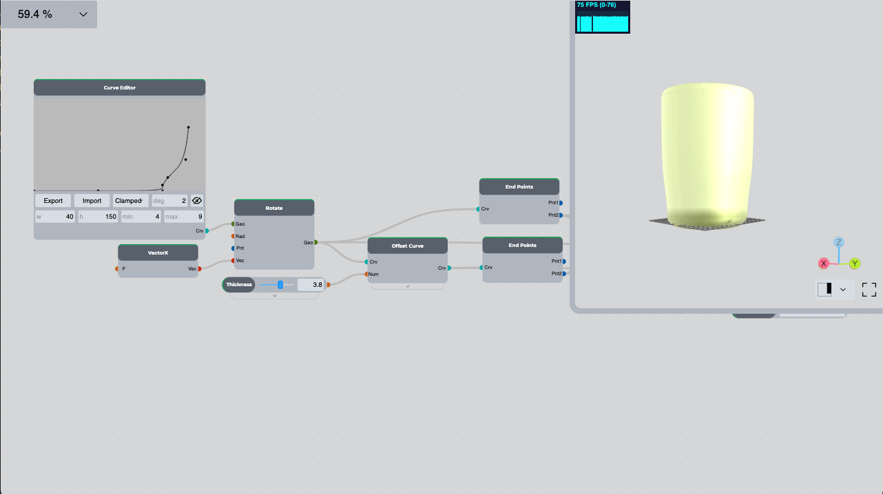
We place the Curve Editor node, change the field size of the Curve Editor, and select the width and height of the cup we need, giving w (width) the maximum value of the cup radius, and h (height) the cup height being the maximum value in millimeters.
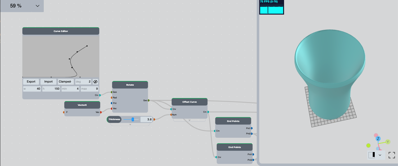
Clicking on the eye in the right corner opens the coordinates of the points, we give 0 to the x coordinates of the first 3 points, respectively, half to the radius of the base of the cup, and we give 0 to the y coordinates so that the bottom of our glass is flat. Starting from the 4th point, we start to shape the look of our cup. To add new items, double-click in the Curve Editor field. After adding a new item, we move it to the place we need. With this curve, we get half of the vertical intersection of the cup in the XY plane.
To get the curve in the XZ plane, place the Rotate node and rotate it. Connect the Curve Editor to the first node of the Rotate node (Geo) and the VectorX node to the fourth node (Vec).
Install the Offset Curve Node and connect the Rotate Node to the first node of the Offset Curve Node (Crv), and the second node (Num) to the wall thickness of the cup. Install the Range Input node, the minimum size of which is 2, and the maximum is 5.
To get the edge of the cup, place two End Points nodes.
Connect the value of the Rotate node to the first, and the value of the Offset Curve node to the second. Insert the Line node and connect it to the second values of the End Points nodes in sequence. We place the Curve Middle Point node and connect the value of the Line node to it. This gives the midpoint of the curve.

To get a curvature, we find the coordinates of the point and change its z value. To do this, we place the Deconstruct Point node and connect the value of the Curve Middle Point node to it. Then we place the Construct Point node and we connect x and y of Deconstruct Point to it, and we add a certain number to the value of z, for example, 5. We place the Addition node and connect the value of z to its first node (A), and the number n to the second node (B), for which we place the Range Input node and give it a value that will be the height of the glass edge.
Install the Interpolate node, increase the number of input nodes by 2 and connect them in order:
- The second value of the End Points node connected to the Rotate node,
- The value of the Construct Point node,
- The second value of the End Points node connected to the Offset Curve node.

To get one complete curve, we place the Join node, increase the number of nodes of the input curves by 1 and connect the following curves to them in order:
- The return value of Rotate node
- The return value of Interpolate node
- The return value of the Offset Curve node.
To get the initial appearance of the cup, we place the Revolve Surface node and connect the value of the Join node to it.

In a 3D view of the model, we see the initial appearance of the glass. By making changes to Curve Editor, you can get the look of the cup you need.
Now we can give material to the glass, for that we place the Material node and connect the value of the Revolve Surface node to its first node (Srf), we hide the value of the Revolve Surface node. We connect the color to the second node (Color), for that we place the Color Input node and select the color. The other 3 nodes of the material node should be connected in the range 0–1, which will give the cup metallicity, roughness and transparency.

The process of algorithmic modeling in BeeGraphy Editor
Modeling instruction by Arman Rashoyan
Software used for 3D parametric modeling: BeeGraphy parametric/algorithmic node-editor.
